 电话:
电话:
 邮箱:
邮箱:


开云手机站登录入口-开云online(中国)的产品
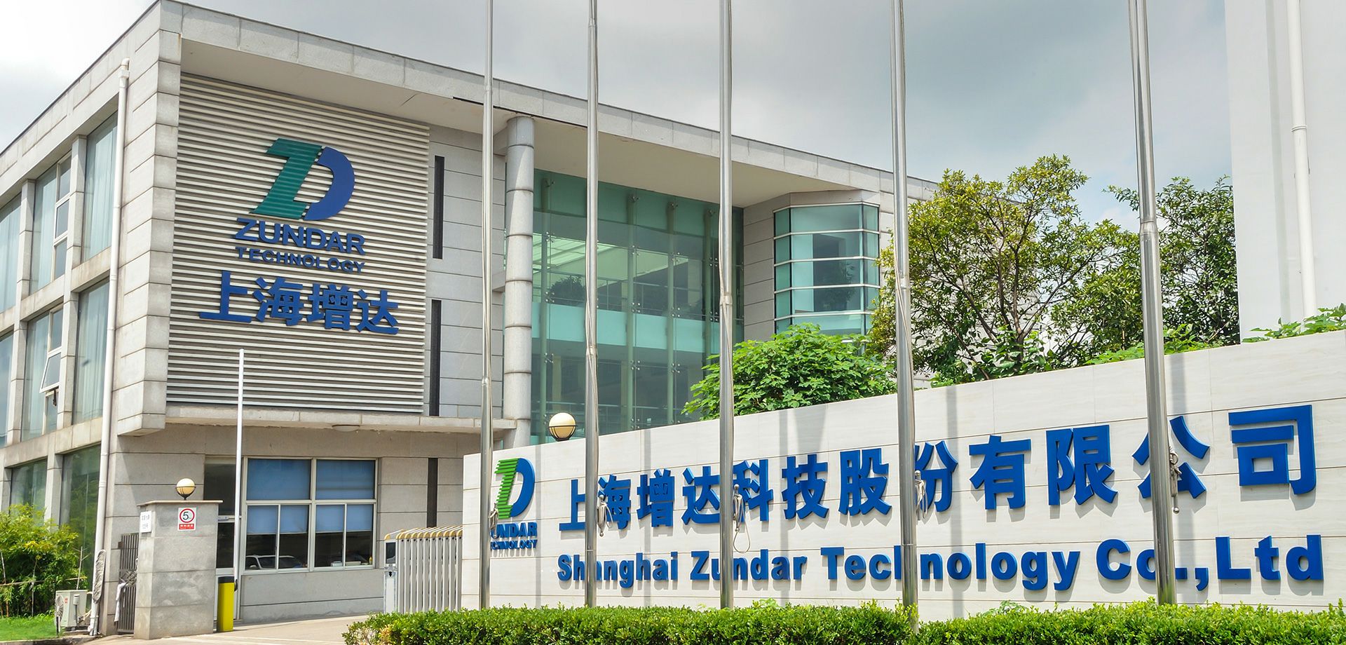
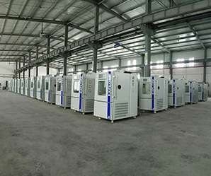
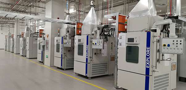
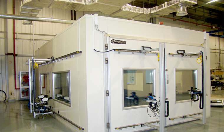
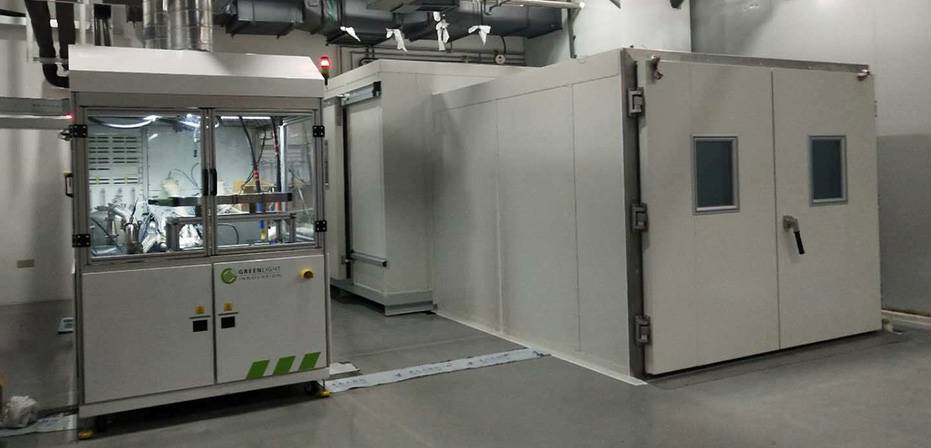
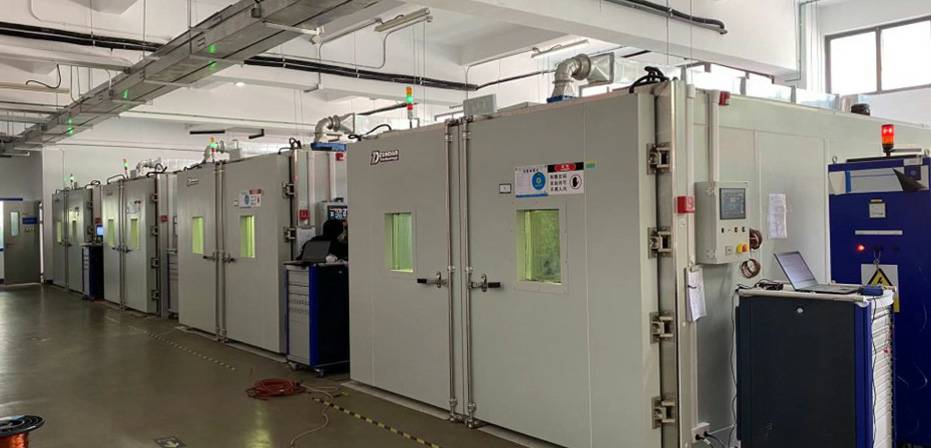
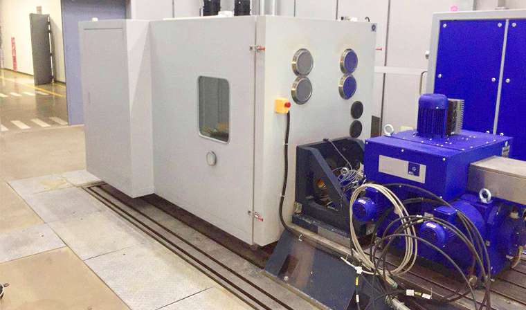
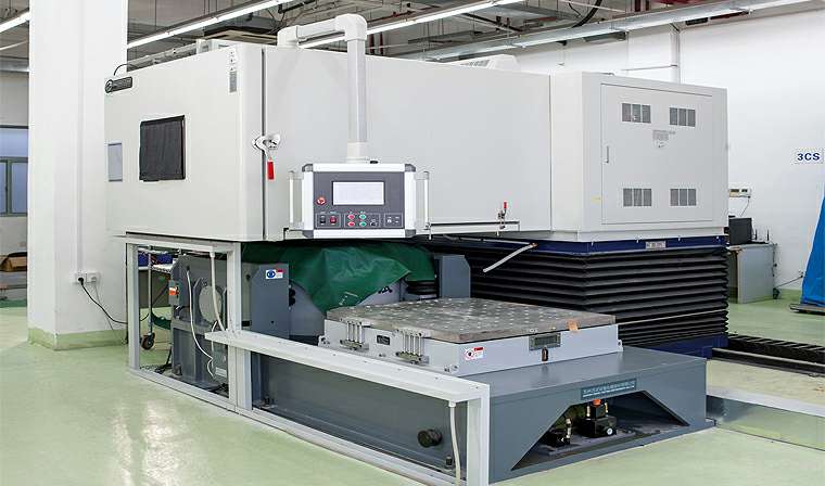
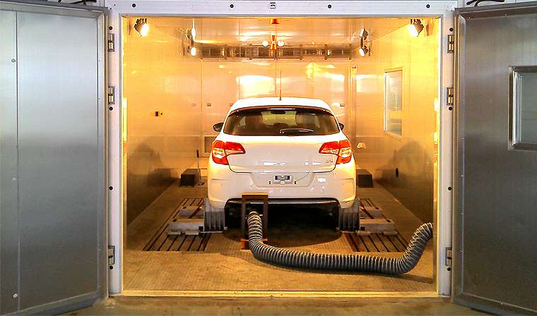
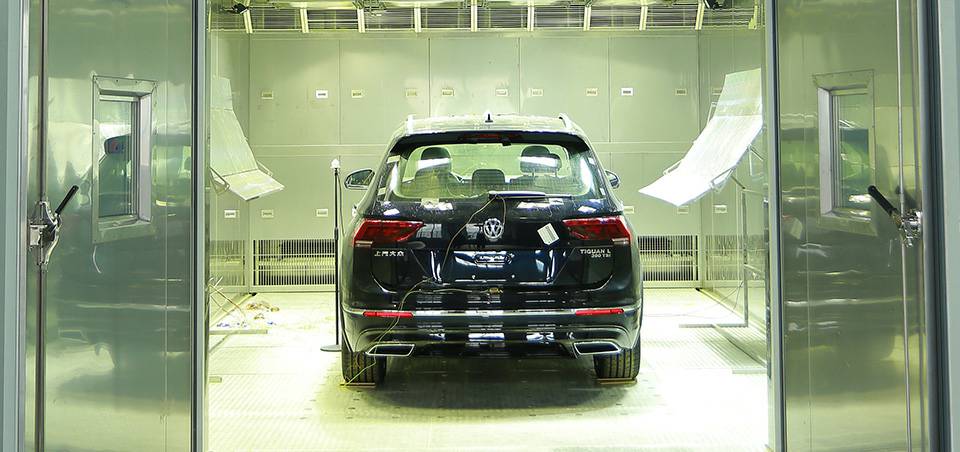
我司在强大的制冷与气候模拟技术力量的基础上,融合了前沿的环境箱控制技术与质量管理流程;竭诚为客户提供可靠,节能,性能优异的环测产品;公司产品已广泛应用于汽车制造、航空航天、军工制造、电子通讯、医药化工、检测计量、科研院校、电子电池等众多领域;同时也致力于光电、光伏、太阳能等新能源行业。
VR展示
了解更多


科技领先
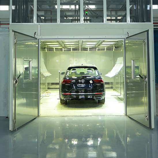
公司产品已广泛应用于汽车制造、航空航天、军工制造、电子通讯、医药化工、检测计量、科研院校、电子电池等众多领域;同时也致力于光电、光伏、太阳能等新能源行业


品质保证
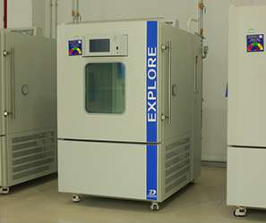
公司在强大的制冷与气候模拟技术力量的基础上,融合了前沿的环境箱控制技术与质量管理流程;竭诚为客户提供可靠,节能,性能优异的环测产品


优质售后
依靠现代化管理模式,秉承“团结协体,求实守信,积极进取,追求卓越”的精神,为客户提供各种环境试验设备和优良服务,产品在中外用户中得到了广泛的好评和信赖


解决方案
依靠现代化管理模式,秉承“团结协体,求实守信,积极进取,追求卓越”的精神
为客户提供各种环境试验设备和优良服务,产品在中外用户中得到了广泛的好评和信赖


新闻资讯
依靠现代化管理模式,秉承“团结协体,求实守信,积极进取,追求卓越”的精神,为客户提供各种环境试验设备和优良服务,产品在中外用户中得到了广泛的好评和信赖
 2021 / 10-12
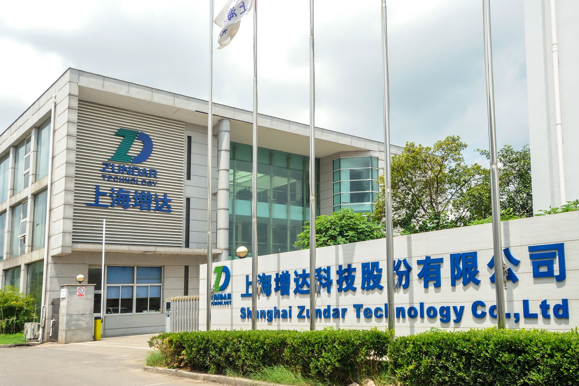
联系我们
您有任何问题可以留言,开云手机站登录入口-开云online(中国)会在三个工作日内给您回复;
或者您也可以直接通过下面的联系方式联系我们!
